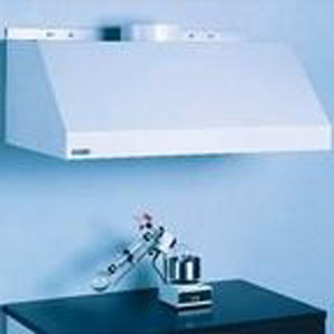
- hood(s),
- ductwork,
- (an) air cleaning device(s)
- and air moving device.
Figure 6-1
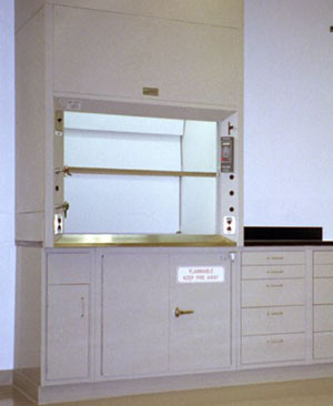
| One of the most effective engineering approaches for the control of air contaminants in industry is the use of local exhaust ventilation (LEV). LEV is a ventilation system comprised of: |
|
|
| These component parts are identified in the illustration below. |
|
|
|
Figure 6-1
|
| LEV systems are designed to collect air contaminants at the source or point of generation before these air contaminants can enter the worker's breathing zone. If LEV systems are designed correctly nearly 100% of the air contaminants can be captured and removed from the work environment so that employee exposures can be kept at or below acceptable levels. |
| There are several reasons why safety professionals and industrial hygienists should consider LEV. |
| For example, LEV systems: |
| 1. remove the air contaminant at the source before it can enter the workers' breathing zones. This control is especially useful when employees are working with highly toxic chemicals that may cause harm from short term (acute) or long term (chronic) exposures. |
| 2. usually requires less volumetric air flow (Q) , measured in cubic feet of air per minute or ft3/min to control employee exposures to air contaminants . Usually less air is required to capture and remove the contaminant at the source than would be required to dilute or exhaust the contaminant after it has been released into the ambient workroom air. |
| 3. can effectively control multiple types/forms of air contaminants. Gases, vapours, and particulate may be effectively removed from the workplace using this method. |
| 4. operating costs are usually less with LEV than general dilution/exhaust ventilation because less air is needed to control the air contaminant. This can result in tremendous cost savings to the employer in terms of energy costs. Remember, workroom air may need to be heated in the winter and cooled in the summer. The cost of heating and/or cooling air is directly related to the volume of air that needs to be treated each day. |
| The use of LEV to control air contaminants has some disadvantages. However, in many situations the advantages far outweigh the disadvantages. |
| Some disadvantages are that LEV systems: |
| 1. must be designed following good industrial hygiene practice to control air contaminants cost effectively and efficiently. |
| 2. can require a larger capital investment up front than general ventilation systems to pay for design, construction and installation materials, |
| 3. may be more complex in design than general ventilation systems, |
| 4. may require a more rigorous maintenance schedule than general ventilation systems. |
| In order to effectively evaluate LEV systems it is important to be comfortable with the manner in which LEV systems are designed. |
| With ventilation systems designers attempt to create pressure differences to control exposures to air contaminants. In LEV systems, designers attempt to create a low pressure zone at the hood opening so that air is drawn into the hood along with the air contaminants released from a process. Furthermore, after the fan, a high pressure zone is created so that the collected air and contaminants can be discharged. |
| By applying these basic principles and understanding some additional concepts, simple or complex systems can be designed. |
| In physics most of us learned that one (1) atmosphere of pressure at standard temperature and sea level is equivalent to the pressure exerted on one square inch by a column of mercury 29.92" high. This pressure would be equivalent to a pressure of 14.7 pounds per square inch. |
| In industrial ventilation, pressure differences are described and measured in terms of inches of water (" of H2O) or inches water gauge ("wg). One atmosphere of pressure (at standard temperature, at sea level) would be equivalent then, to the pressure exerted on one square inch of surface by a column of water approximately 407 inches high. Pressures above 407" of H2O are referred to as positive pressure while those below are referred to as negative pressure conditions. |
| Static pressure is defined as potential pressure exerted in all directions by a fluid at rest. For a fluid in motion it is measured in a direction normal or perpendicular to the direction of flow. Furthermore, it can be visualized to some degree as the tendency to collapse or burst the ductwork. In short, depending upon where one measures static pressure, it can be 0, positive or negative. That is it can be equal to, above or below atmospheric ambient pressure, respectively. |
|
Velocity pressure is defined as the kinetic pressure exerted in the direction of flow necessary to cause a fluid at rest to flow at a given velocity. |
|
VP is also described and measured in inches of H2O or inches water gauge. Velocity pressure is exerted in the direction of flow, is always positive (i.e. greater than atmospheric pressure) when a fluid is moving, and is measured in the direction of airflow. It is also related to velocity by the following formula: V = 4005 ( Square Root of VP) |
| Using this formula , the velocity of air at any point in the ventilation system can be determined by taking a velocity pressure reading. |
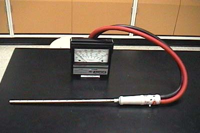
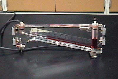
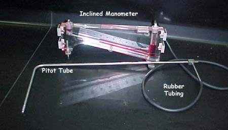
| It is important to understand that VP is not uniform across the duct. In short, air tends to move faster near the centre and slower near the walls of the duct. Therefore, VP measurements will vary when a series of measurements are made when conducting a duct traverse using a pitot tube. (This topic will be discussed in greater detail later under the Ventilation Testing section of this module). |
|
The last head component that evaluators of LEV systems must be aware of is total pressure. Total pressure (TP) is simply the algebraic sum of SP and VP. That is: TP = SP + VP |
| TP, like SP and VP, is described or measured in terms of inches of H20 water or inches water gauge ("wg). Therefore, TP can be zero, positive or negative when compared to ambient atmospheric pressure. |
|
The relationship between TP, VP and SP can be found in the illustrations below. |
|
|
| When an LEV system is fitted the designer must take into consideration several important factors. These factors include: |
|
| Safety professionals must consider the process when designing any ventilation system. The location, size, number and design of hoods, duct work, air cleaning device(s), fan(s), and discharge stack(s) will be influenced by process parameters such as the number of emission points, available space, employee access needs, and the specific chemical/physical properties of the air contaminant(s). |
| For example, systems can be designed to remove gases/vapors, particulate, or both. The volumetric air flow rate required to collect these air contaminants and transport them through the LEV system, with adequate duct velocity, can vary considerably. Generally LEV systems require less air to control gases/vapors than heavy particulate (e.g. grinding dust). |
|
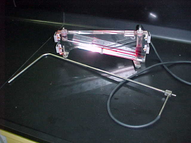
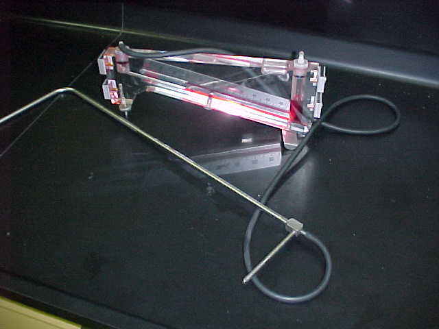
There are many different hood designs to choose from. |
| Hood placement is also an important consideration. Generally, hoods should be located as close to the point of air contaminant release as practicable to maximize air contaminant capture and removal. |
| In general LEV hoods fall into four categories: |
|
|
|
|
|
|
|
|
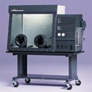
Glove Box
|
|
|
|
|
|
Canopy Hoods
|
|
|
|
|
| Within an LEV system it is important to determine the volumetric air flow rate (Q) that is needed to create a sufficient capture velocity in front of the hood. The capture velocity that is created in front of the hood entry must be sufficient to capture the contaminant and draw it into the hood and away from the worker's breathing zone. |
|
Volumetric airflow rate (Q) is described in cubic feet of air per minute or ft3/min. In LEV systems it is not usually measured directly but is calculated. The formula which follows is used to make this determination: |
|
Q= AV |
| Where: Q = the volumetric airflow rate in ft3/min |
|
|
|
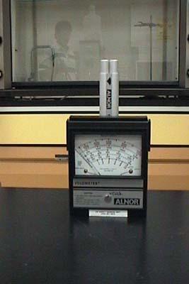
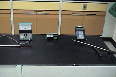
5. Testing LEV Systems
Velocity (V) Determinations
Static Pressure Measurements
Velocity Pressure Measurements
Total Pressure Measurements
|